 |
|
|
Software
for Refrigeration, Airconditioning &
Energy technology |
| |
| Cooltool
- Modules |
|
CoolTool
Modules summary |
|
This software system gives quick and easy
results for direct practical use. It makes
quick comparison between the big amount
of CFC substitutes possible, and a lot
of smaller and bigger calculations, from
the psychrometric chart up to the complete
design of a the air conditioning for a
building.
Calculations of air flow rates, cooling
capacities for cold rooms, and for air
conditioning are possible. It designs
one- and two stage compression circles
and their parts in an easy way with the
new and old refrigerants. Compound plants
with direct evaporation, with secondary
refrigerants, or with flooded evaporation
are feasible up to 40 evaporators, or
cooler.
After the estimation of the properties
of the refrigerant there is a true scale
h, log p - Diagram. The software considers
the glide of the refrigerant blends by
using the evaporation temperature to in
the middle of the useable enthalpy.
All calculations are made in one clear
window, with contains the main influence
parameters. The power input because of
the thermodynamic process for the estimation
of the costs of performance and the selection
for all necessary tubes will be done by
the software. Changes in the dimensions
of the tubes with be calculated immediately,
and the influence on the main properties
like filling amount, discharge temperature,
necessary displacement of the compressor
or total capacity will be displayed.
The results will be summed up in part
lists for tubes, valves, aggregates and
reductions, which makes the disposition
of materials and die calculation of the
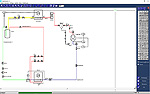
plant costs easier. System flow diagrams
and electric wireing are easy to make
with the added symbols.
|
|
 |
Modul
1: Onestage compression refrigeration
plants |
 |
Pipe layout
for steel- and coppertubes, for
suction-, discharge-, liquid-, expansion-,
condensing and hotgas bypass line
in consideration of pressure loss,
velocity and particular run.
|
|
Lay out double
riser tube for proof oil return.
|
|
Display of the
thermodynamic process in the h,
log p - diagram.
|
|
Estimating of
the energy consumption and CO2 emissions
dependent on the construction and
the performance of the plant
|
|
more than 30
different refrigerants, calculation
of the influence of the temperature
glide for refrigerant blends.
|
|
Compressor design
in consideration of the necessary
displacement, variation: reciprocating,
scroll or screw; open, semi hermetic,
or hermetic.
|
|
Component design
for eighteen different kinds of
parts from the CoolTool Database,
graphical display of the parts.
|
|
Creation of part
lists for tubes, valves, aggregates
and reductions.
|
|
Creation of an
automatic system flow diagram with
selected parts.
|
|
Summary of all
relevant technological and ecological
information in the printout
|
|
Project and part
list management.
|
|
Interface to
CoolTool cold room, air conditioning
load, to CoolTool h,x - chart; Interface
to CoolDraw for electric wireing
and system flow diagrams.
|
|
|
|
Modul
2: Twostage compression refrigeration
plants |
|
Pipe lay out
for steel- and copper tubes, for
suction-, discharge-, liquid-, expansion-
and condensing line in consideration
of pressure loss, velocity and particular
run for high- and low pressure part
of the plant.
|
|
Display of the
thermodynamic process in the h,
log p - diagram.
|
|
Estimating of
the energy consumption and CO2 emissions
dependent on the construction and
the performance of the plant.
|
|
More than 30
different refrigerants, calculation
of the influence of the temperature
glide for refrigerant blends.
|
|
Calculation and
display of the optimum average pressure.
|
|
Compressor design
in consideration of the necessary
displacement, variation: reciprocating,
scroll or screw, open, semi hermetic,
or hermetic.
|
|
Component design
for eighteen different kinds of
parts from the CoolTool Database,
graphical display of the parts.
|
|
Creation of par
tlists for tubes, valves, aggregates
and reductions.
|
|
Summary of all
relevant technological and ecological
informations in the printout.
|
|
Project and part
list management.
|
|
Interface to
CoolTool cold room, air conditioning
load, to CoolTool h,x - chart; Interface
to CoolDraw for electric wireing
and system flow diagrams.
|
| |
|
|
|
|
Modul
3: Compound plants with direct evaporation |
|
Pipe lay out
for steel- and coppertubes, for
suction-, discharge-, liquid-, expansion-
and condensing line in consideration
of pressure loss, velocity and particular
run.
|
|
Tube framework
for up to 40 evaporators possible.
|
|
Graphic illustration
and print out of the tube framework:
CoolTool quick scheme or detailed
drawing in a ground plan.
|
|
Lay out double
riser tube for proof oil return.
|
|
Display of the
thermodynamic process in the h,
log p - diagram.
|
|
Estimating of
the energy consumption and CO2 emissions
dependent on the construction and
the performance of the plant.
|
|
More than 30
different refrigerants, calculation
of the influence of the temperature
glide for refrigerant blends.
|
|
Compressor design
in consideration of the necessary
displacement, variation :reciprocating,
scroll or screw, open, semi hermetic,
or hermetic.
|
|
Component design
for eighteen different kinds of
parts from the CoolTool Database,
graphical display of the parts.
|
|
Creation of partlists
for tubes, valves, aggregates and
reductions.
|
|
Project and part
list management.
|
|
Summary of all
relevant technological and ecological
information in the printout.
|
|
Interface to
CoolTool cold room and air conditioning
load. Interface to CoolTool h, x
- chart. Interface to implement CoolDraw for
electric wireing and system flow
diagrams.
|
|
|
|
Modul
4: Compound plants with secondary refrigerants |
|
Pipe lay out
for steel-and copper tubes, for
flow- and return line in consideration
of pressure loss, velocity
|
|
Tube framework
for up to 40 cooler possible.
|
|
Variation of
every single tube possible.
|
|
Graphic illustration
and print out of the tube framework:
CoolTool quick scheme or detailed
drawing in a ground plan.
|
|
Calculation of
pressure drop of the heat exchanges/fan
coils.
|
|
Consideration
of the hydraulic balance and pressure
regulations valves.
|
|
Calculation of
the mixture from necessary freeze
security.
|
|
Component design
for seven different kinds of parts
from the CoolTool Database, graphical
display of the parts.
|
|
Main information
for pump lay out.
|
|
Creation of par
tlists for tubes and reductions.
|
|
Project and part
list management.
|
|
Interface to
CoolTool cold room and air conditioning
load. Interface to CoolTool h,x
– chart. Interface to implement CoolDraw
for electric wireing and system
flow diagrams.
|
| |
|
|
|
|
Modul
5: Compound plants with flooded evaporation |
|
Pipe lay out
for steel- and copper tubes, for
suction-, discharge-, liquid-, expansion-
and condensing line in consideration
of pressure loss, velocity and particular
run.
|
|
Pipe lay out
on the evaporator side for steel-
and copper tubes, for flow- and
return line in consideration of
pressure loss, velocity and particular
run.
|
|
Tube framework
for up to 40 evaporators possible.
|
|
Consideration
of two phase flow.
|
|
Variation of
every single tube possible.
|
|
Graphic illustration
and print out of the tube framework:
CoolTool quick scheme or detailed
drawing in a ground plan.
|
|
Lay out double
riser tube for proof oil return.
|
|
Display of the
thermodynamic process in the h,
log p - diagram with consideration
of the circulation rate.
|
|
Estimating of
the energy consumption and CO2 emissions
dependent on the construction and
the performance of the plant.
|
|
More than 30
different refrigerants, calculation
of the influence of the temperature
glide for refrigerant blends.
|
|
Compressor design
in consideration of the necessary
displacement, variation reciprocating,
scroll or screw, open, semi hermetic,
or hermetic.
|
|
Component design
for eighteen different kinds of
parts from the CoolTool Database,
graphical display of the parts.
|
|
Creation of part
lists for tubes, valves, aggregates
and reductions.
|
|
Project and part
list management.
|
|
Interface to
CoolTool cold room and air conditioning
load. Interface to CoolTool h, x
- chart. Interface to implement CoolDraw for
electric wireing and system flow
diagrams.
|
|
|
|
Modul
6: h,x - chart for handling of air humidity |
|
Graphic display
of the connection of temperature,
relative and absolute humidity,
enthalpy and density as Mollier
or Ashrae.
|
|
Zoom of the graphic
display.
|
|
Lay out double
riser tube for proof oil return.
Permanent calculation of the properties
by moving the mouse.
|
|
Calculation of
the properties for condition change.
|
|
Mixture of two
air flows.
|
|
Calculation
of latent and sensitive power.
|
|
Display and calculation
of complete air process with cooler,
heater and humidifier.
|
|
Variation of
all important process points with
mouse scroll buttons and immediate
calculation and graphic display
in the chart.
|
|
Output of the
calculation data to CoolTool plant
design.
|
|
Print out h,
x-chart in colour.
|
|
|
|
Modul
7 : Cooling load for cold rooms |
|
Necessary cooling
load from different shares in consideration
of temperature,
specific heat capacity before and
after solidification, solidification
enthalpy and respiration heat.
|
|
Cooling good
database with editor.
|
|
Consideration
of the air exchange rate from the
number of entries.
|
|
Outside- and
inside air condition with relative
humidity.
|
|
Calculation of
the temperature difference in the
evaporator.
|
|
Evaporator design
in consideration of the electric
power of the fan from the CoolTool
database.
|
|
Individual construction
of wall with calculation of the
heat transmission from building
material database.
|
|
Output of the
calculation data to CoolTool plant
design.
|
|
Data of the storage
are saved together with the plant
information in the main projekt
in the CoolTool plant design software.
|
|
|
|
Modul
8: Cooling load for air conditioning |
|
Necessary cooling
load from shares of the different
internal and external loads like
heat transmission, sun radiation,
air exchange, persons and electrical
power.
|
|
Consideration
of the latent and sensitive enthalpy.
|
|
Change of the
geografical data for calculation
of the specific sun radiation.
|
|
Consideration
of the store capacity of the walls.
|
|
Consideration
of the air exchange with outside
and inside air humidity.
|
|
Individual construction
of wall with calculation of the
heat transmission from building
material database.
|
|
Output of the
calculation data to CoolTool plant
design.
|
|
Data of the storage
are saved together with the plant
information in the main projekt
in the CoolTool plant design software.
|
|
|
|
Modul
9 : CoolDraw with technical libraries |
|
Drawing tool
with zoom function.
|
|
Graphic library
EN 1861 for system flow diagrams.
|
|
Graphic library
DIN 40 900 for electric wire schemes.
|
|
Graphic library
with pictos of components.
|
|
Extension of
the library by the user is possible.
|
|
Single files
can be saved.
|
|
Connected with
CoolTool projects.
|
|
Colored printout.
|
|
|
|
Modul
10: HeatPump Pro Heatpump facilities |
|
heat demanded pipe dimension for steel- and copper pipe for Suction, pressure,liquid, injection and condensate pipeline after pressure loss, flow speed and part load operation.
|
|
Dimensioning double rising pipelines with critical oil return, Economizer/Steaminjection operation, hot gas defrosting
|
|
Display of the thermo-dynamic comparative process in the h, log p diagramme
|
|
more than 30 refrigerants, consideration of the Temperaturglides on mixed refrigerants
|
|
Compressor dimensioning according type possible: Piston, croll or Screw, openly, semi-hermetic or full-hermetik component dimensioning from the CoolTool database with graphically displaying of the components
|
|
Compilation of parts list for conduits, armatures, aggregates and reductions
|
|
Automatically creation of a RI - Assembly-line Sketch with the chosen components
|
|
Conformance Declaration of Pressure Equipment Directive (PED) and ECO Design Directive
|
|
Project and part list management
|
|
Interface to CoolTool climate load and heating load calculation and h, x diagram
|
|
Determine operating expenses-/energy consumption with worldwide available climate data
|
|
|
|
Modul
11: CoolTool plant calculation |
|
Masterdata for determination of assambling time and business calculation.
|
|
Parts lists export and assign assembly time after type, size and pipe connection
|
|
Stammdaten für
Kupfer-, Stahl, PVC- und GF-Rohr,
bis zu 15 Positionen für Kleinteile
je Rohrdimension
|
|
Gaining data from cool tool parts list with selectfunktion
|
|
Summarize of the same positions
|
|
Whole calculation of all components with profit margins for material and wages
|
|
Copy and paste export to MS Excel
|
|
Export function of ASCII/ANSI file format
|
|
|
|
Modul
12: CoolTool EnerSIm Pro Energy optimisation |
|
Simulation of the comparative process from one-stage, multicompressor systems and
refrigerant plants
|
|
Operating expenses analysis with variable condensing temperature
in the annual and day-by-day way
|
|
Masterdata for plant utilisation and run time
|
|
Variations of controlling type, winter regulation, plant maintenance, facility filling
|
|
Climate data throughout Europe/Worldwide
|
|
Documentation and graphic representation
|
|
|
|
Modul
13: CoolTool MonoFlow |
|
CoolTool for Monoflow Parallel/Booster systems with direct evaporation in two temperature levels
|
|
Pipe lay out for steel- and copper tubes, for suction-, discharge-, liquid-, expansion - and condensing line in consideration of pressure loss, velocity and particular run for two temperature levels
|
|
Tube framework for up to 80 evaporators possible.
|
|
graphic illustration and print out of the tube framework in a ground plan
|
|
Lay out double riser tube for proof oil return..
|
|
Display of the thermodynamic process in the h, log p - diagram.
|
|
Estimating of the energy consumption and CO2 emissions dependent on the construction and the performance of the plant
|
|
more than 40 different refrigerants including CO2 trans critical, calculation of the influence of the temperature glide for refrigerant blends..
|
|
Compressor design in consideration of the necessary displacement, variation :
reciprocating, scroll or screw, open, semi hermetic, or hermetic. .
|
|
Creation of part lists for tubes, valves, aggregates and reductions
|
|
Creation of an automatic system flow diagram with selected parts
|
|
Project and part list management.
|
|
Summary of all relevant technological and ecological information in the printout
|
|
Summary of all relevant technological and ecological information in the printout
|
|
Interface to CoolTool cold room and air conditioning load.
Interface to CoolTool h, x - chart.
Interface to CoolDraw for automatic system flow diagrams
|
|
|
|
Modul
14: CoolTool Database |
|
More than 8000
parts from AC&R, Alco, Airwell,
Alfa Laval, Bitzer, Bock, Castel,
Carly, Carrier, Copeland, Danfoss,
Delchi, Dorin, Eco, ESK, FAS, Frascold,
Flica, Friga-Bohn, GAR s.r.l., Goedhart,
Hansa, Helpman, Honeywell, ITE,
Küba, L’Unite, Maneurop,
Necchi, Roller, Searle, Sporlan,
Technibel,... to be calculated,
designed and compared with the software.
|
|
Selection of
the compressors by reel thermodynamic
conditions.
|
|
Selection of
the evaporators by consideration
of the EUROVENT Standards.
|
|
Valves are calculated
by using the k, v – value
and the pressure loss.
|
|
|
|
|
|
|
|
|